






Bringing the CNC Router Back to Life: a VFD Replacement Story
 Written byMohamed Slimani
- CategoryElectronics
- Date
- Reading8 min
The day the spindle stopped
This one started with a call: a client's CNC router had stopped, and he asked us to fix it. His CNC router cuts forex (PVC foam) sheets, and he had left the machine cutting unattended. The plastic protective wrap on the sheet caught the spindle and wrapped around it until it jammed. After that, the spindle would not run at all.
Bigger, faster machines cut straight through that film. But at low spindle speed, or with the wrong bit, the film can come loose and start winding around the bit while it is still stuck to the sheet. Each turn pulls it tighter, until the wrap is strong enough to stop the spindle completely.
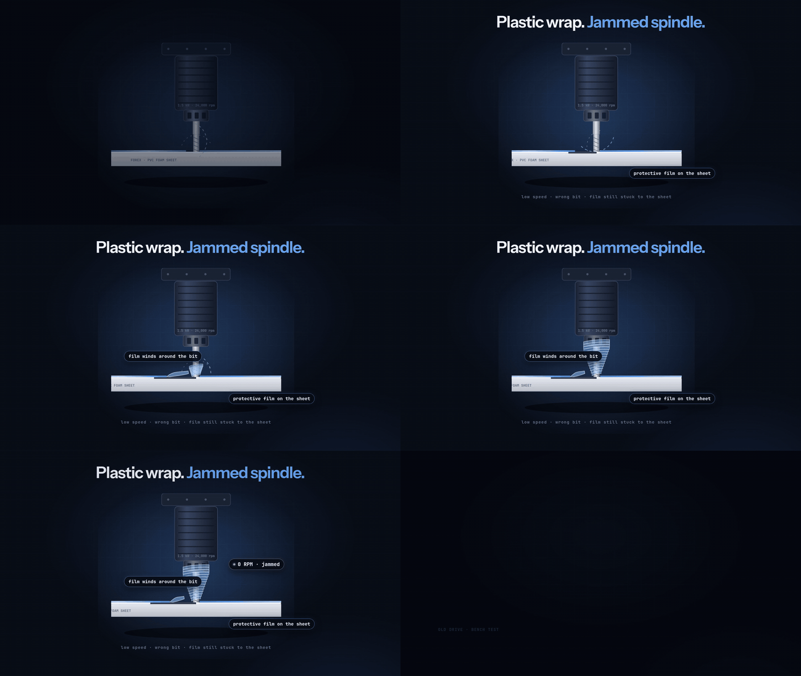
A jammed spindle is a worst case for the drive. It keeps pushing current into a motor that cannot turn, and something has to give.
The spindle is a 1.5 kW, 220 V motor that runs at 400 Hz, which means 24,000 rpm. A VFD turns the workshop's single-phase 220 V into the three-phase, high-frequency power it needs. When the spindle dies, the first question is always: is it the motor, the drive, or the wiring between them?
Finding the culprit
The spindle was healthy; the old drive was not. We tested from the motor back toward the drive, ruling out one part at a time.
| Check | What we measured | Verdict |
|---|---|---|
| Spindle windings | 2.4 Ω on all three pairs, nothing to ground | Motor is fine |
| Supply | 213 V AC in, 295 V on the DC bus | Power is fine |
| Old drive output stage | W leg dead; diode test N→W read 1.4 V instead of a normal diode drop | Drive is damaged |
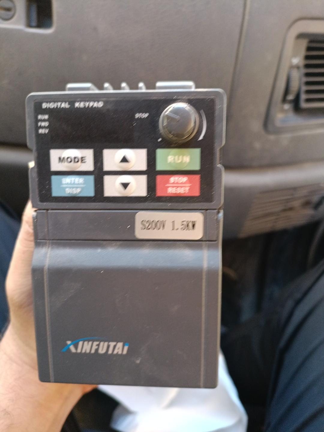
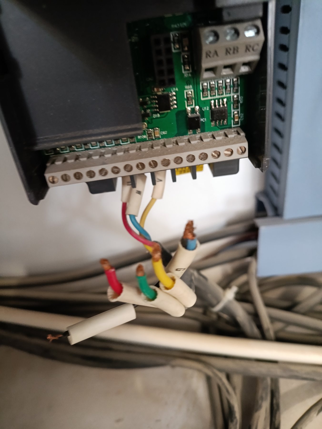
The old drive was a Xinfutai FT-S001521KD: 1.5 kW, single-phase 220 V in, three-phase 7 A out, 0.1–400 Hz. One of its three output legs, W, had failed. A drive with a dead output leg can't make three-phase power, so the spindle can't turn. The jam is the most likely cause: a blocked motor draws a heavy current through the output transistors.
Repair or replace?
We replaced it. Fixing a dead output leg means replacing the power module, and whatever killed it may have damaged the driver board too. For a 1.5 kW drive, that repair is not worth the parts, the time and the risk.
The new drive is a Nietz AT20-1R5G-2, a close match to the old one:
| Old: Xinfutai FT-S001521KD | New: Nietz AT20-1R5G-2 | |
|---|---|---|
| Power | 1.5 kW | 1.5 kW |
| Input | 1-phase 220 V | 1-phase 220 V |
| Output | 3-phase 220 V, 7 A | 3-phase 220 V, 7 A |
| Frequency range | 0.1–400 Hz | 0.1–599 Hz |
Same power, same input, same output current, and enough frequency range for 400 Hz. On paper it was a drop-in replacement. In practice, every drive brand numbers its settings differently, and that is where the trouble started.
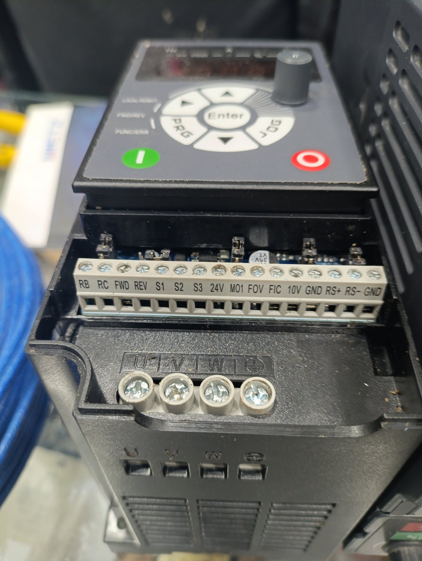
Copying the old drive's brain
The dead drive still had one thing to give: its settings. Its keypad still worked, so we read every value that mattered before taking it out.
| What | Old drive |
|---|---|
| Run command | From the terminals (P101 = 1) |
| Max / base frequency | 400 Hz (P105, P110) |
| Accel / decel | 10 s (P107, P108) |
| Motor | 220 V, 7.0 A (P109, P210) |
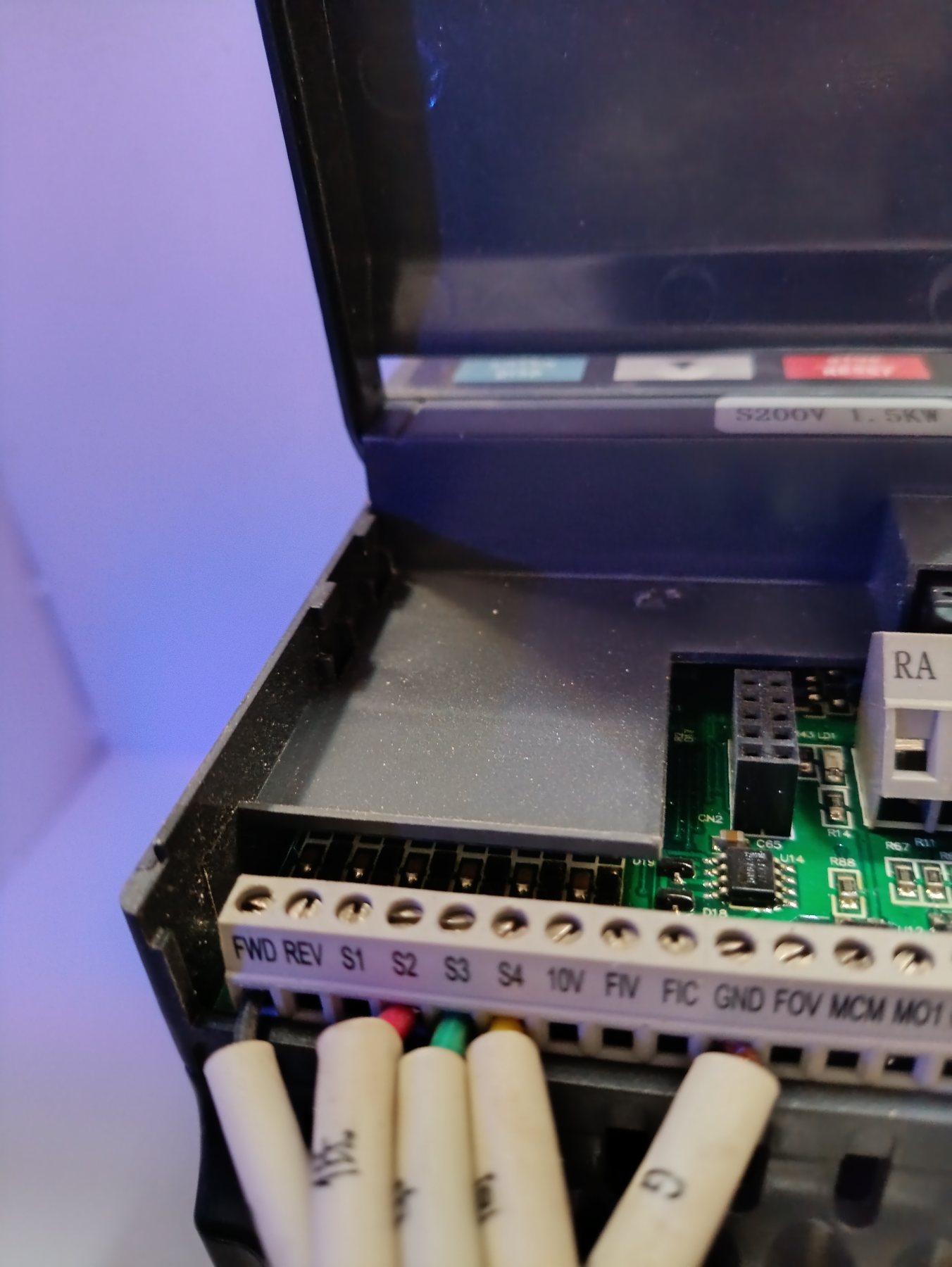
| Inputs | FWD = run; S2, S3, S4 = speed bits 1, 2, 3 |
| Speed table | 0, 100, 150, 200, 250, 300, 350, 400 Hz |
This showed how NC Studio talks to the drive. One wire says "run", and three wires form a 3-bit number from 0 to 7 that picks one of eight preset speeds. Speed 0 is 0 Hz; speed 7 is full speed, 400 Hz.
The plan was simple: move each wire to the matching terminal on the new drive (S2, S3, S4 became S1, S2, S3), then enter the same values. The hard part was finding where those values live on the AT20.
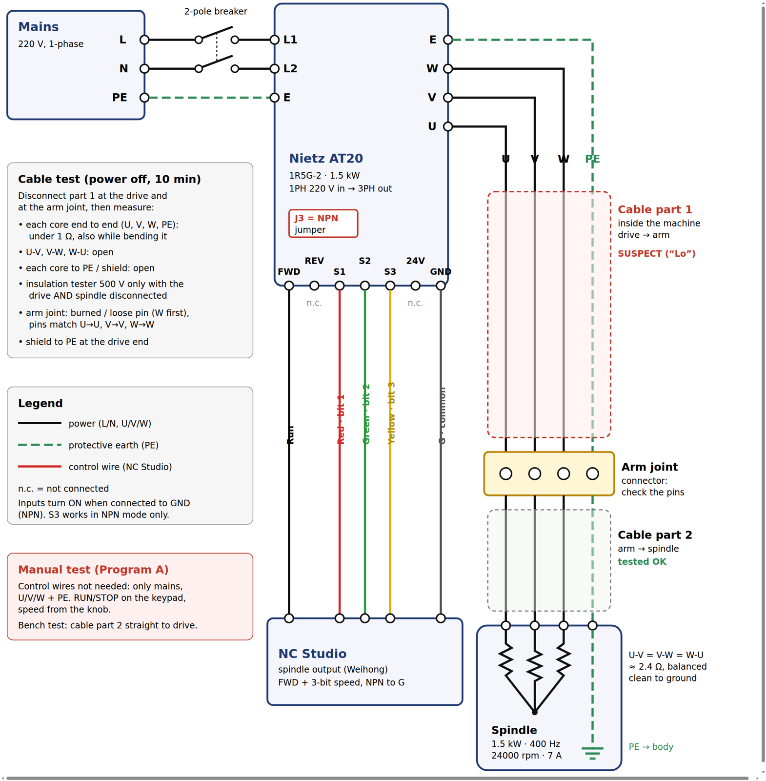
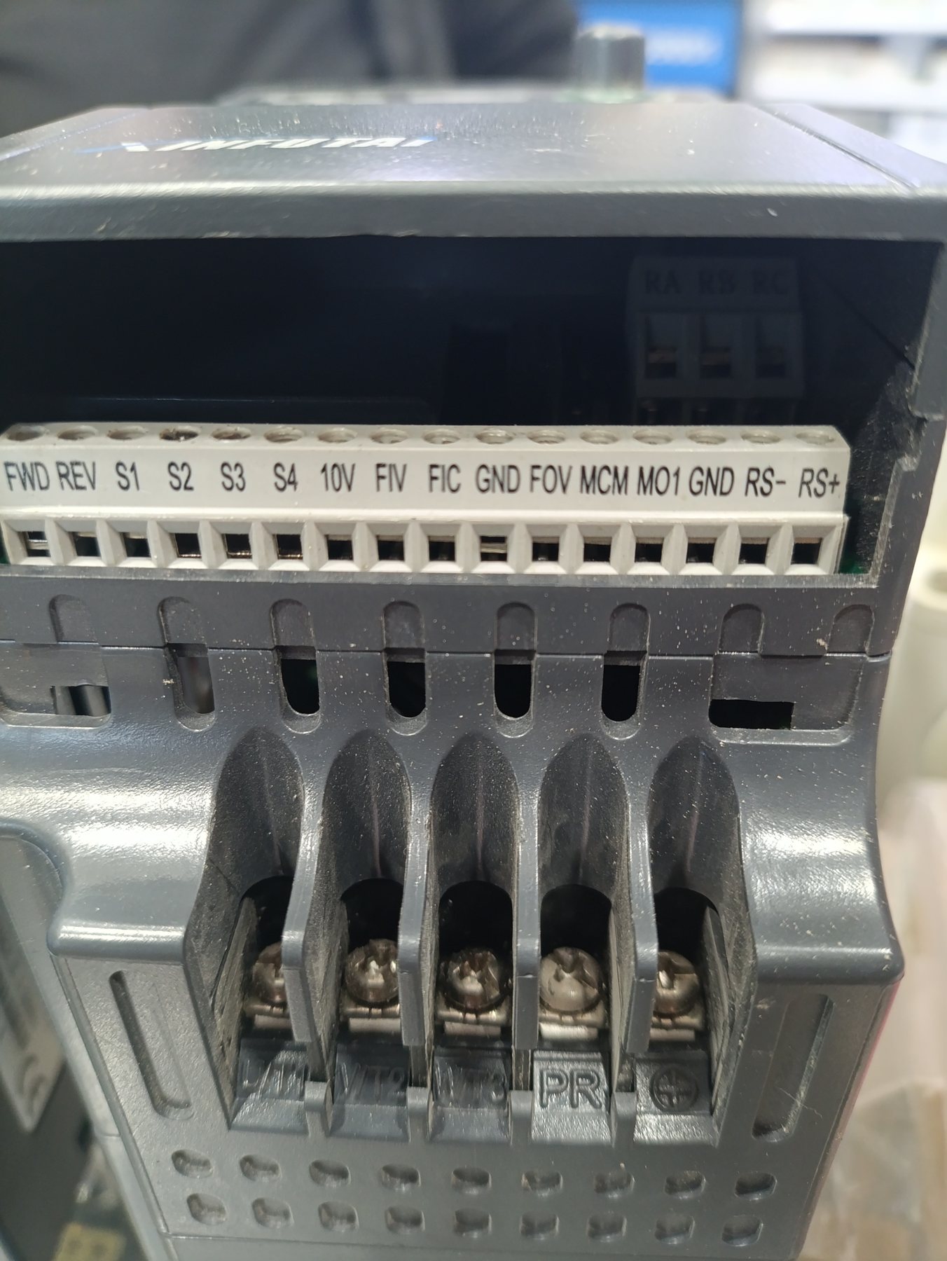
When nothing made sense
The new drive fought us at every step, and for a while every fix created a new problem. Without the manual, we set the parameters by the numbering a common Chinese drive brand uses, assuming the AT20 followed it. It doesn't.
Stuck at 50 Hz, then an OL2 trip. The maximum frequency would not go past the factory 50 Hz, and the drive tripped on OL2 (drive overload). We had been changing the wrong parameters.
Every start ended in "Lo". It first appeared each time NC Studio sent the run command. Later it appeared even on a manual run, with NC Studio out of the loop.
Bridging S1 to ground did nothing. Even a direct test of the first speed input had no effect.
The manual fought back too. The manual is a 13 MB, 180-page scanned PDF with no searchable text, too large for ordinary web tools to open. We had to download it and run text recognition on it before we could search it.
Each symptom pointed somewhere different, and the machine sat idle the whole time. This was the low point.
Reading the real manual
Once we could search the manual, every symptom had a plain explanation.
The numbering was different. On the AT20, max frequency is P0.10, the frequency source is P0.03, motor data is P1.01–P1.05, and the inputs are P4.xx. We had been writing to the wrong parameters.
S1 did nothing because of its factory setting. Out of the box, S1 is a fault-reset input (function 9), not a speed bit.
"Lo" is not "low". It is a fault code: output phase loss. The drive saw one of U, V or W missing or unbalanced and refused to run.
That last one mattered most. The old drive had lost its W leg, so the wiring to the spindle was now a suspect too.
Splitting the problem in half
The spindle cable comes in two parts: one runs inside the machine to a joint at the arm, the other runs from the arm to the spindle. We stripped all the wires and started the tests over, beginning with a manual run. For this bench test, we connected only the arm-to-spindle part straight to the drive, with no control wires. Speed came from the keypad knob.
It ran perfectly. So the drive and the spindle were both fine, and the cable inside the machine, or its joint at the arm, became the main suspect for "Lo".
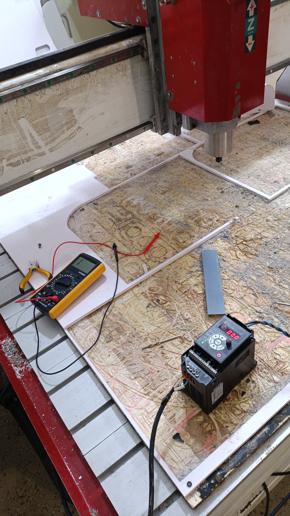
One more surprise: for the knob to work, P0.03 had to be 4. One page of the manual calls 4 "reserved", but its summary table says 4 is the keypad knob on drives up to 5.5 kW.
Teaching it NC Studio's language
With the right numbers, the multi-speed setup went in cleanly:
| Parameter | Value | Meaning |
|---|---|---|
| P0.02 | 1 | Run command from the terminals |
| P0.03 | 6 | Speed from the multi-speed inputs |
| P0.10, P0.12 | 400 Hz | Max frequency and upper limit |
| P0.17, P0.18 | 10 s | Accel and decel |
| P1.01–P1.05 | 1.5 kW, 220 V, 7 A, 400 Hz, 24000 rpm | Motor nameplate |
| P4.02, P4.03, P4.04 | 12, 13, 14 | S1, S2, S3 = speed bits 1, 2, 3 |
| PC.01–PC.07 | 25 % to 100 % in 12.5 % steps | 100 to 400 Hz in 50 Hz steps |
The speed table is in percent of the 400 Hz maximum, not in Hz. We tested it first with a jumper wire on each input, then from NC Studio, one speed level at a time. Every level gave the right frequency.
The last twist: a spindle that wouldn't let go
At speed 0, the spindle hissed and was hard to turn by hand. On this machine, FWD is wired permanently to ground, so the drive is always "running"; NC Studio stops the spindle by choosing speed 0. The drive was holding the motor at 0 Hz, with a little voltage on the windings.
We tried telling the drive to stop below 10 Hz (P0.14 = 10, P8.14 = 1). The hiss went away, but so did the spindle: once stopped, the drive waits for the run signal to switch on again, and a permanently wired FWD never does. We put both settings back to 0, and the spindle worked again.
Back to cutting
The router is running again: NC Studio starts the spindle, and every speed level from 100 to 400 Hz matches the old drive. All the settings, the wiring diagram and the test tables are now on a 4-page setup sheet, kept with the machine.
What we would tell anyone doing the same job:
Never leave the machine cutting unattended. A loose wrap or offcut can jam the spindle in seconds, and a jammed spindle kills drives.
Read the old drive's settings before removing it. That table was the whole plan.
Get the exact manual for the new drive. Parameter numbers differ between brands, even when they look alike. Guessing cost us the most time.
Read fault codes as fault codes. "Lo" meant phase loss, not "low".
Split the problem in half. Testing with the short cable and the knob separated the drive, the spindle and the wiring in one step.
Know how the run signal is wired. With FWD always on, "stop at low speed" settings stop the spindle for good.
Sources
Tags :
- CNC
- VFD
- Spindle
- NC Studio
- Troubleshooting
- Electronics